Rotary Encoder Switch
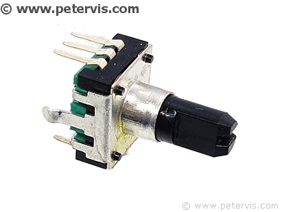
A rotary encoder is a switch used for selecting menu options, and is used in amplifiers as an electronic rotary volume control. It often resembles a potentiometer with three pins; however, these can be rotated 360-degrees. An encoder detects the direction of the rotation of shaft, and the speed of rotation. When the shaft rotates clockwise, the left pin produces pulses, and when the shaft rotates counter-clockwise, the right pin produces pulses. This gives a microcontroller system information about direction of rotation. The rate of the pulses generated provides information about the speed of rotation.
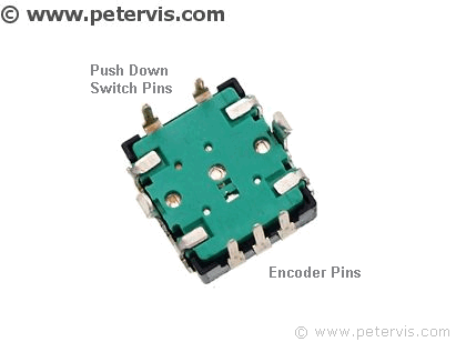
Whilst the early encoders had three pins, most of the modern ones manufactured in China have five pin as they also contain an additional switch. This additional switch is depressed when the shaft is pushed down. The idea behind this is that you rotate the shaft in order to select a menu option, and then press down on it to choose the option.
I managed to find the cheapest one on eBay from a seller who was selling five for two pounds, however these are the five pin ones. After a long trawl of all the data sheets, I managed to find out that the five pin encoders can be used in place of three pin ones. You just do not use the two terminals for the additional pushdown switch! Luckily, the arrangement for the pins is such that there are three pins on one side with the centre pin as the common. These three pins are for the encoder function. The two pins for the pushdown switch, situated on the other side of the component, are not used.
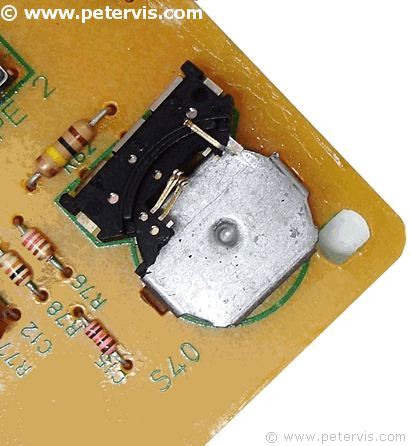
As you can see, the original encoder had broken off with the base plate still soldered to the PCB. There was also a crack with broken tracks.
This was the input selector switch. The information from this went into the microcontroller, which then did the actual switching of the audio input signal.
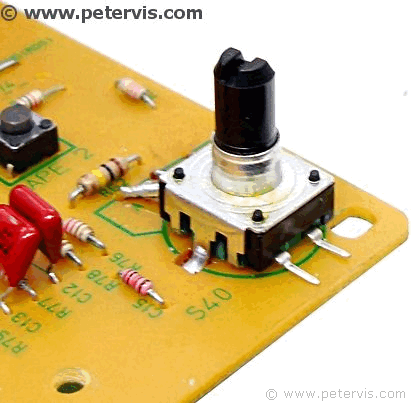
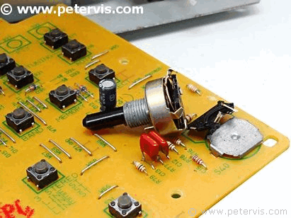
As you can see here, I have soldered a new encoder switch. The common terminal is the centre pin on this encoder, however on the PCB; the side pin is the common. Hence, I had to make a small modification for this to work.
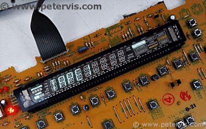
After hours of soldering, and repairing the PCB tracks, I managed to get the input selector to change to tape input.
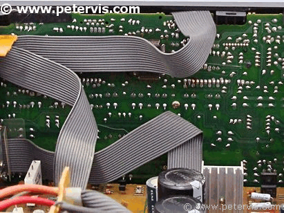
This is the PCB on the front part of the amplifier. On mine, it is damaged, so if anyone has one of this together with the front plastic panel then let me know.
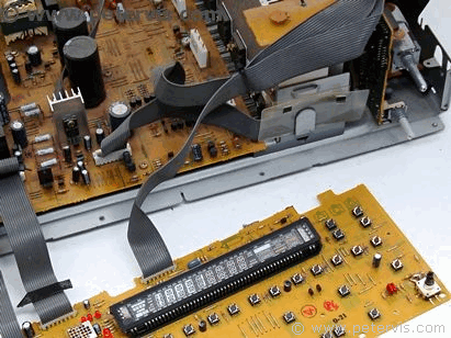
Here is the front PCB.
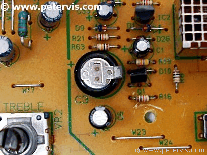
There is a battery, which keeps the memory contents alive when the amplifier is unplugged. The memory stores the volume and input settings.
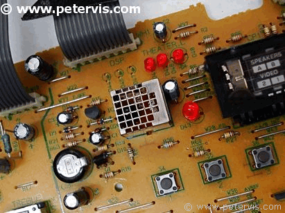
This is the infrared module for the remote control. Alas, no remote control...
This Article Continues...
Kenwood KR-V6060Kenwood KR-V6060 Review
Kenwood KR-V6060 Broken by Courier
2SB1470 and 2SD2222 Power Transistors
Kenwood KR-V6060 Inside Look
Kenwood KR-V6060 Back Connectors
Rotary Encoder Switch
Kenwood KR-V6060 Power Supply
Kenwood KR-V6060 Receiver Tuner
