bigtrak Circuit Diagram - Encoder Servo
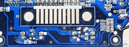

If you are a Raspberry Pi user, it is perfectly fine to rip out the main PCB and install your own dual H bridge driver chip to drive the motors. I think I saw some projects where people did just that. You can also buy a ready-made motor driver PCB with the chip, on eBay. They cost as little as £1.20 including postage!
The great thing about the gearbox transmission of this toy is that the motor shafts are magnetically coupled, thus keeping synchronisation. Hence, simply driving the motors without the servo will still allow the vehicle to move in a straight line -- for a short distance anyway.
For a six year old, a toy rolling on the ground controlled by a Raspberry Pi is fine; however, if you need precise controlled movement you will need to learn how the servo works, and how to use it. I decided to use the servo already installed on this toy, and I simply needed to tap into the points where the encoder pulses were. In this design, the encoder circuitry does not remain powered all the time. Presumably, this is to save battery power, however, it is possible to enable this part of the circuitry manually.
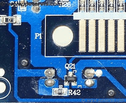
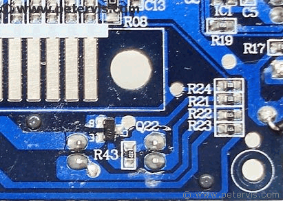
Here is an enlarged view of the PCB. It took me a few minutes to figure out that the couplers are reversed; hence, their pinouts will be reversed. However, once I figured that out, everything fell into place.
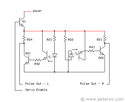

Here is my reverse engineered circuit. I drew it around the pinouts of the couplers exactly as you would see it on the PCB, hence the crossed lines on the schematic. I could turn the components around in my schematic, but I think it is easier to visualise it this way.
As you can see from the circuit diagram, the encoder pulses come from the collector terminals of Q21 and Q22. Click on the first photograph at the top of this article to see the exact points on the PCB.
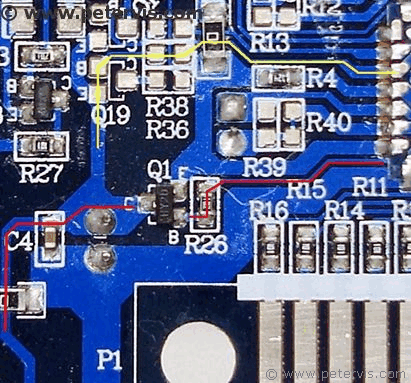
To enable the servo encoder part of the circuitry, a saturating signal at the base junction of Q1 switches it ON hard. This provides power to the couplers and the associated circuitry as shown in the circuit diagram. You could of course hot-wire this part of the circuitry to remain powered all the time; however, it is not necessary, as it is just a matter of wiring another control line to whatever controller that blows your hair back.
As you can see from the picture above, the red line indicates a signal from the controller chip passing through R26 and into the base junction of Q1. Injecting a signl there will enable the servo encoder circuitry. Ignore the yellow line; this is just something I was thinking of which involves Q19 and a cluster of missing components. I think it is for a hidden function that the factory did not enable... I might write about it in another article if I get the time.
This Article Continues...
bigtrakbigtrak Commands
Opening the bigtrak
bigtrak Gearbox
bigtrak Motor
bigtrak Circuit Board
bigtrak Encoder
bigtrak Power Switch
bigtrak Removing the Wheels
bigtrak Facelift - The bigBrit Mod
bigtrak Facelift Modification
bigtrak Circuit Diagram - H Bridge Motor Driver
bigtrak Circuit Diagram - Encoder Servo
bigtrak Circuit Hack
bigtrak Speaker - Battery - LED - Wiring
bigtrak Ribbon Cable
bigtrak With Raspberry Pi
bigtrak Battery Cover and Compartment
bigtrak Front Suspension Mod
bigtrak Modifications Log
bigtrak Painting Wheel Rim Modification
Buying a bigtrak
