bigtrak Encoder
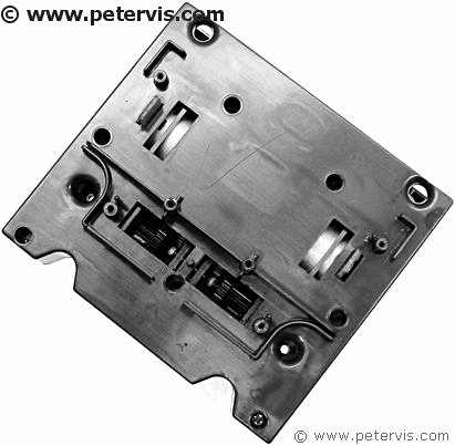
The top side of the gearbox transmission has cut out windows for the optical couplers, and the encoder disc positions between the slots of the coupler.
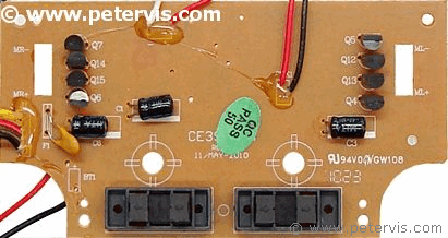
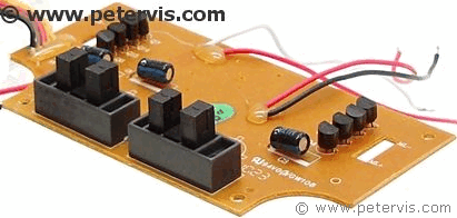
The encoder consists of a MOC7811 type slotted coupler, in a 354A style case. There is an infrared LED at one end facing a phototransistor at the other. A slot between the two provides a means to interrupt the light beam; hence, this component is an optical interrupter switch.
The part that interrupts the light beam is an encoder disc, also known as an interrupter disc as well. In this assembly, the encoder disc integrates into the final stage cogwheel, which has holes through it.
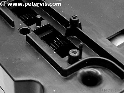
As you can see, the last stage of the gear assembly also doubles as an encoder disc. This cogwheel is between the phototransistor and LED and interrupts the beam of light from the LED.
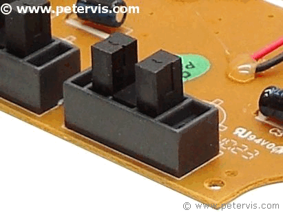
This is a 354A style coupler, sometimes also called a Phototransistor Optical Interrupter Switch.
Closed Loop Servo System
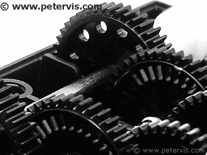
As the wheel turns, the phototransistor will output a train of pulses. The number of pulses received indicates to the servo algorithm how far the drive shaft shown above rotated.
The main purpose of an encoder disc and optical assembly is to form a closed loop servo system using a DC motor. The pulses from the phototransistor provide feedback information to the servo algorithm. The servo system appears to be software based in this toy.
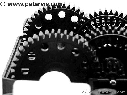
Based on what I have seen, the encoder disc of this toy has 12 holes, 30º apart. Therefore, the servo control has a 30º precision. If the input value to the servo was to move the shaft by 30º, then it could do it. It would provide just enough power to the motors so that it received one pulse from the phototransistor. A 60º rotation would be two pulses. The great thing about a servo circuit is that it compensates depending upon the error value calculated from the feedback. Let us say you wanted the shaft to move 90º. That is three pulses from the phototransistor, however, the DC motor overshoots and you end up getting 4 pulses, then the algorithm is designed to calculate the error value, which would be 1 pulse in this case, and apply that by reversing the motors.
Essentially, the top paragraph is the basis of an algorithm, if you understood it... For some of you it will take seconds, for others, the terms of your natural lives... Servo controlled movement can give the appearance of "Intelligence" because the movements can be small, precise, and controlled, similar to biological life forms. If one were to drive the motors of this toy directly, without servo, the movements would be clumsy. This is because there is no feedback information to tell the system precisely how much the shaft actually moved. Since the two motors are independently driven, it would be difficult to make the toy go in a straight line either. Depending upon the number of hits, this article gets, and if I have the time, I might publish my software based closed loop servo system that I used in my modification.
This Article Continues...
bigtrakbigtrak Commands
Opening the bigtrak
bigtrak Gearbox
bigtrak Motor
bigtrak Circuit Board
bigtrak Encoder
bigtrak Power Switch
bigtrak Removing the Wheels
bigtrak Facelift - The bigBrit Mod
bigtrak Facelift Modification
bigtrak Circuit Diagram - H Bridge Motor Driver
bigtrak Circuit Diagram - Encoder Servo
bigtrak Circuit Hack
bigtrak Speaker - Battery - LED - Wiring
bigtrak Ribbon Cable
bigtrak With Raspberry Pi
bigtrak Battery Cover and Compartment
bigtrak Front Suspension Mod
bigtrak Modifications Log
bigtrak Painting Wheel Rim Modification
Buying a bigtrak
