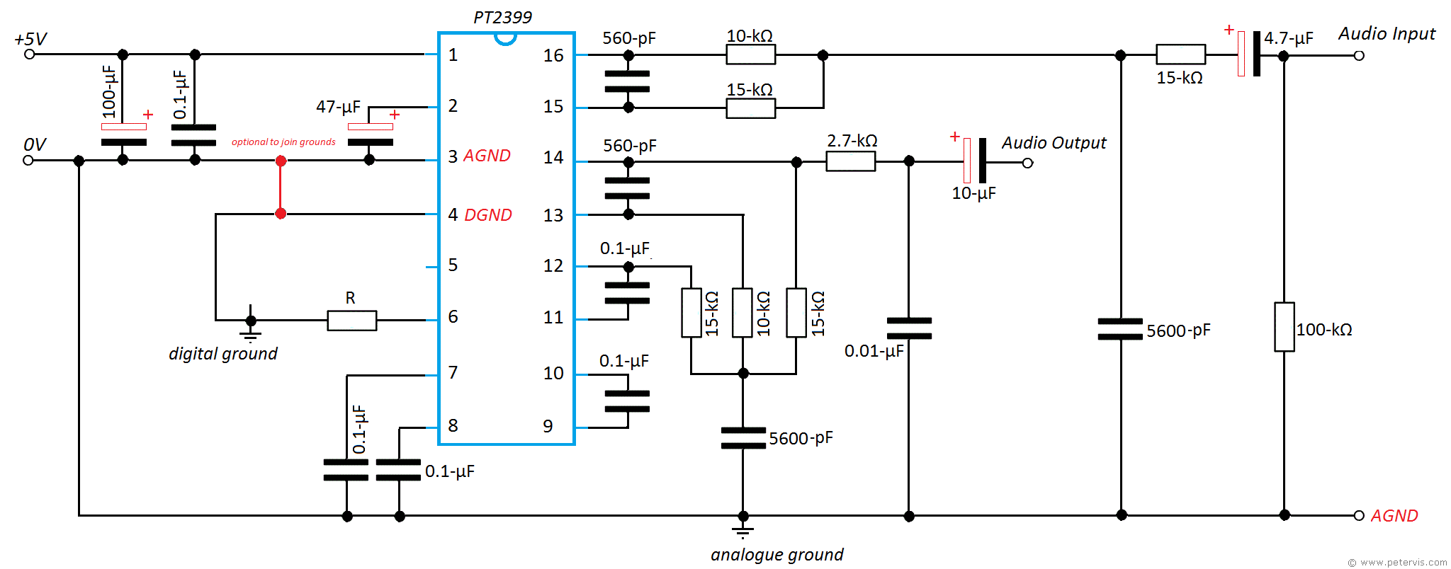
PT2399 Basic Surround Delay Circuit
The basic PT2399 surround/delay circuit produces only a delay that could be used for many purposes besides a guitar effect. This circuit will not produce echoes since the delayed output from pin 14 is not fed back into the input through pin 16. Therefore, this circuit will produce just a continuous delayed output without the initial input since the two are not mixed together as they are in the first op-amp stage (LPF1) of the echo circuit.
These types of circuits tend to be used with surround sound systems and therefore the filters are not so harsh allowing for a better sound quality, but at the risk of introducing more aliasing noise. A continuous delay is useful in surround sound systems where the most favourable sitting position is when the listener is equidistant from all the speakers. This way, the sound from all the speakers reaches him at the same time. However this seldom happens as the back and front speakers tend to be much further away and the centre speakers tend to be too close. Consequently, the sound from the nearby centre speakers reaches the listener first. To solve this problem a slight delay is introduced to the centre speakers using this type of circuit.
In a stereo system, if the one channel produces a slightly delayed output, it can also give the illusion of greater spatial separation between the speakers. For guitar effects such as reverb, the delayed output of this circuit has to be mixed with the original input signal using an additional summer op-amp circuit.
Interestingly, for this delay circuit, the delay control at pin 6 is a fixed resistor instead of a variable resistor, and the manufacturer shows a table of resistor values for R and achievable delay times. Also the table shows this resistor value to range from 27.6-kΩ to 0.5-Ω. There is no mention of any limitations on the resistance values.
This Article Continues...
Echo and Reverb BasicsGuitar Reverb
Basic Surround Delay Circuit
Basic Echo Circuit
PT2399 Overall Configuration
Testing and Troubleshooting
Pin 6 Hack
Pete's Guitar Reverb Circuit
Track Cuts
Board Links
Circuit Board Component Layout
Completed Board
Switch and Potentiometer Wiring
Chip Socket
Power Supply Circuit Diagram
Power Supply Board Layout
Power Supply Board Cuts and Links
Power Supply Board Completed
Enclosure Preparation
Guitar Reverb Completed Project
Connecting and Testing
