PT2399 Guitar Reverb Completed Project
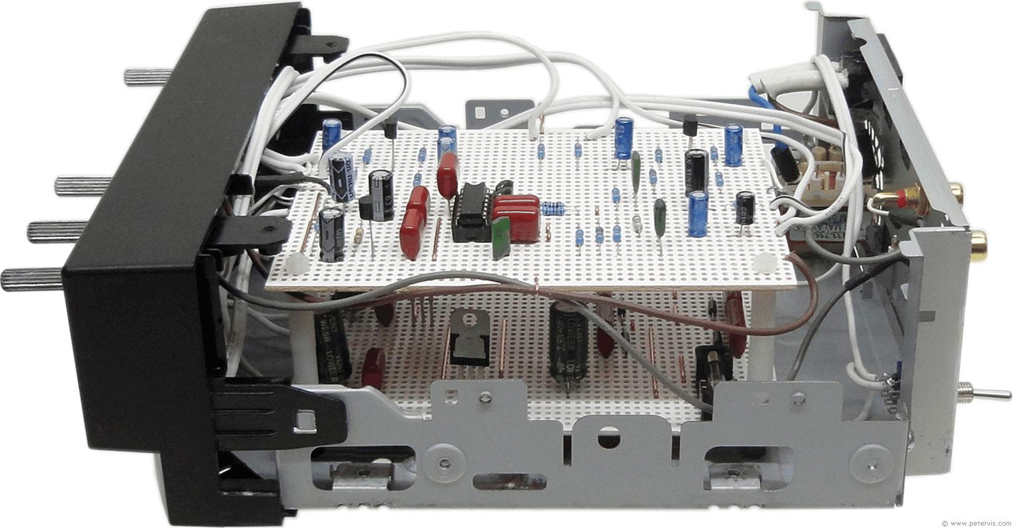
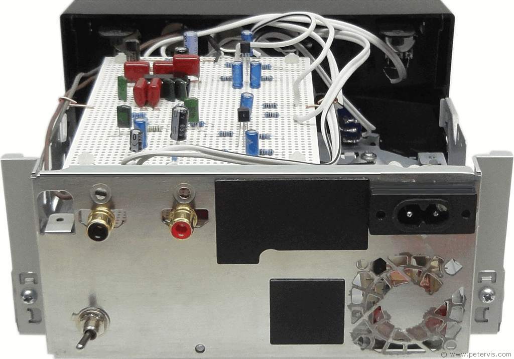
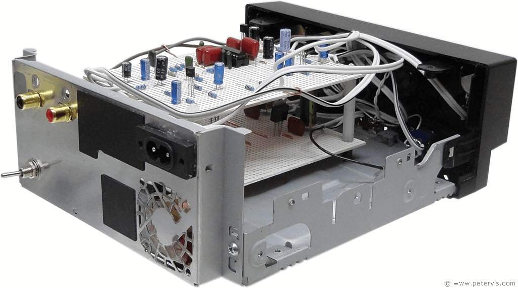
Here are some photographs showing the PT2399 guitar reverb circuit and its power supply board installed within a recycled enclosure. In order to make is small, I had to stack the boards using acrylic hex risers. I would have preferred an enclosure that could accept a 3-core mains wire with earth, but this one with 2-pin figure-8 socket works fine. The overall sound quality and performance was better than I had expected.
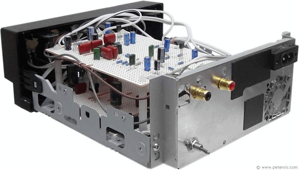
Building this PT2399 guitar reverb circuit was no problem for me. As usual, I ordered the components on eBay, and whilst waiting for them to arrive I decided to redraw the circuit diagram and make a simple strip-board layout. As the capacitors started arriving I made small adjustments to the board layout so that they would fit without having to bend the leads too much. The 0.1-µF capacitors are the 100 V ones with 5-hole spacing. I was very pleased they fitted straight away without too much fuss. After building the main board, I set about building the power supply board. I then installed it all in a small metal case together with a mains transformer. After assembly, I flicked ON the power switch and it all worked first time without any problems.
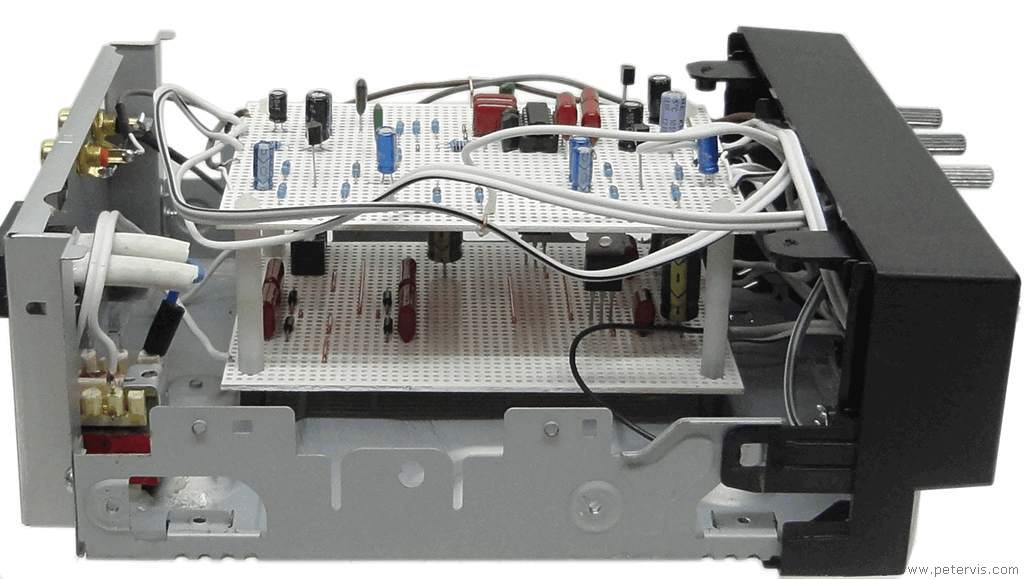
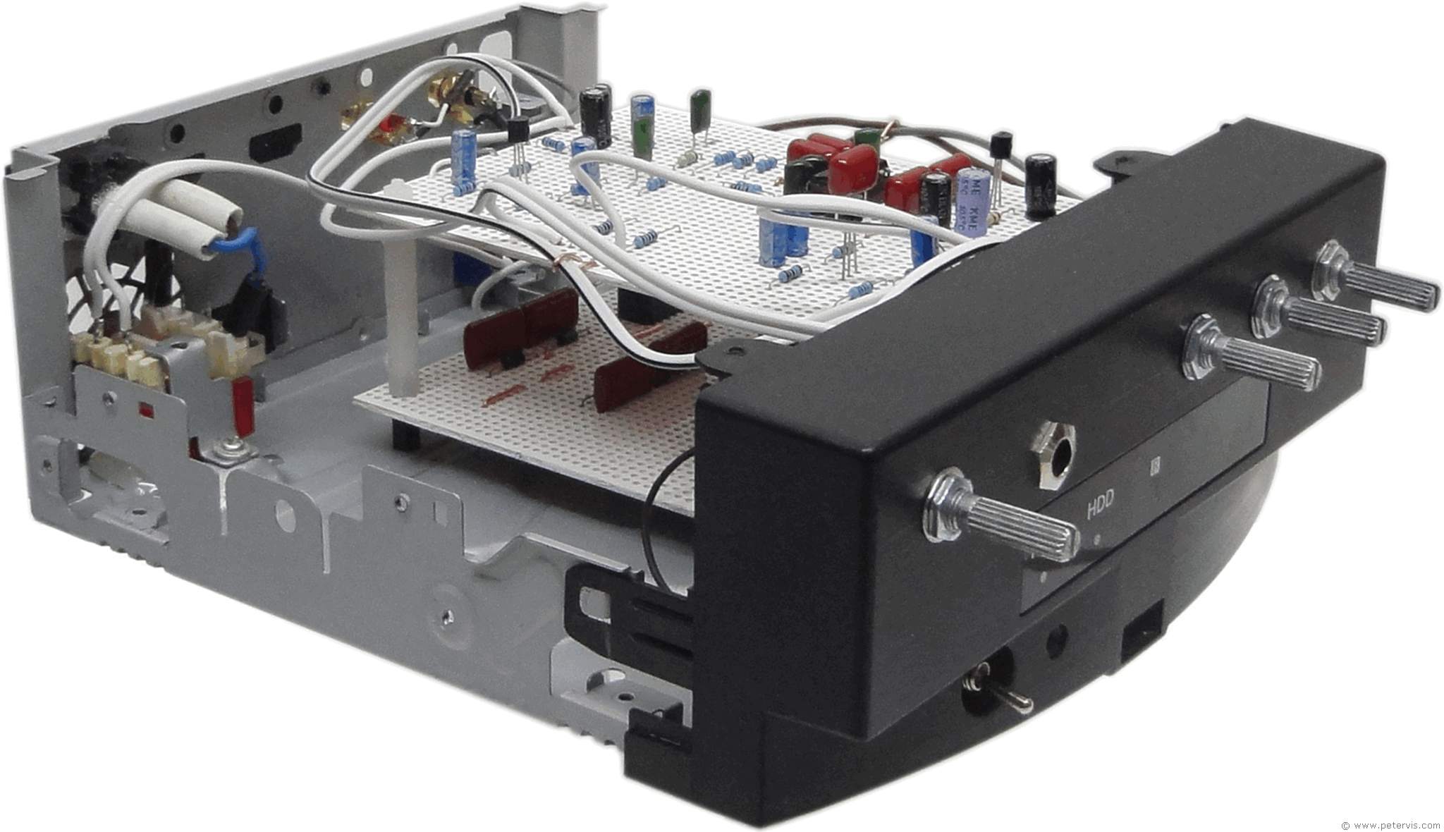
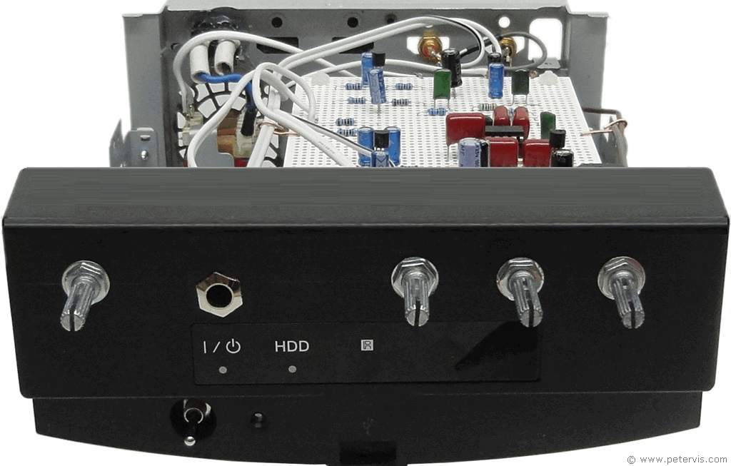
This Article Continues...
Echo and Reverb BasicsGuitar Reverb
Basic Surround Delay Circuit
Basic Echo Circuit
PT2399 Overall Configuration
Testing and Troubleshooting
Pin 6 Hack
Pete's Guitar Reverb Circuit
Track Cuts
Board Links
Circuit Board Component Layout
Completed Board
Switch and Potentiometer Wiring
Chip Socket
Power Supply Circuit Diagram
Power Supply Board Layout
Power Supply Board Cuts and Links
Power Supply Board Completed
Enclosure Preparation
Guitar Reverb Completed Project
Connecting and Testing