PT2399 Reverb Circuit -- Switch and Potentiometer Wiring

Wiring these potentiometers (also known as pots for short) is fairly straightforward if you follow this diagram. The delay variable resistor (VR1) requires only two wires, which is simple to implement. The other three pots have one lug that connects to the analogue ground, hence this is simple to implement with a single wire connecting them all in a daisy-chain fashion. Once you have wired the common ground, then it is just two wires per potentiometer.
Potentiometers
| Component Type | Quantity | Value | Description |
| Variable Resistor VR1 | 1 | 20-kΩ | Linear |
| VR2 | 1 | 50-kΩ | Linear |
| VR3 | 1 | 500-kΩ | Linear |
| VR4 | 1 | 500-kΩ | Linear |
| Misc | 1 | Switch | SPDT |
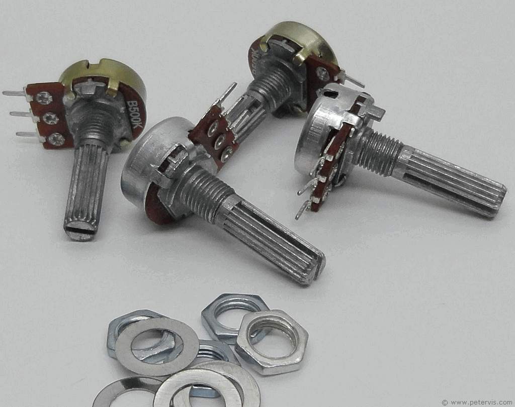
I managed to get these cheap pots on eBay and for the most part, they seem to work fine. If you are going to solder the wires directly on their lugs, then keep the heat to minimum. If you cannot find a 20-kΩ potentiometer, then 50-kΩ one works just as well. In the end I used a 50-kΩ pot for the delay control because I needed the shaft lengths to be the same for the enclosure I was going to use.
This Article Continues...
Echo and Reverb BasicsGuitar Reverb
Basic Surround Delay Circuit
Basic Echo Circuit
PT2399 Overall Configuration
Testing and Troubleshooting
Pin 6 Hack
Pete's Guitar Reverb Circuit
Track Cuts
Board Links
Circuit Board Component Layout
Completed Board
Switch and Potentiometer Wiring
Chip Socket
Power Supply Circuit Diagram
Power Supply Board Layout
Power Supply Board Cuts and Links
Power Supply Board Completed
Enclosure Preparation
Guitar Reverb Completed Project
Connecting and Testing
