PT2399 Reverb Circuit -- Chip Socket

For the PT2399 guitar reverb circuit, I decided to use a chip socket so I could test other versions of this IC in the future. I have ordered ICs from The Far East and this board will provide me the chance to see how well they perform.
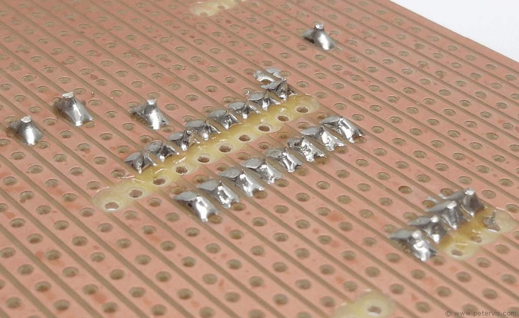
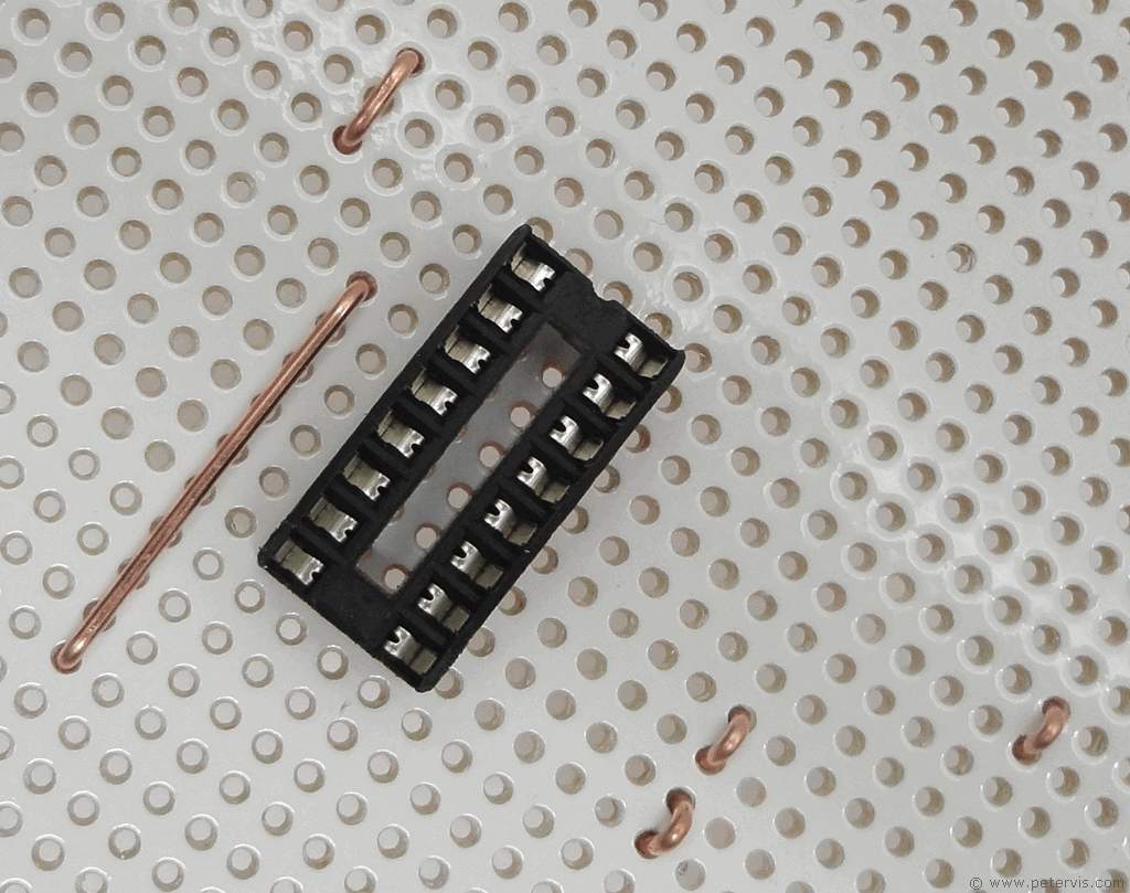
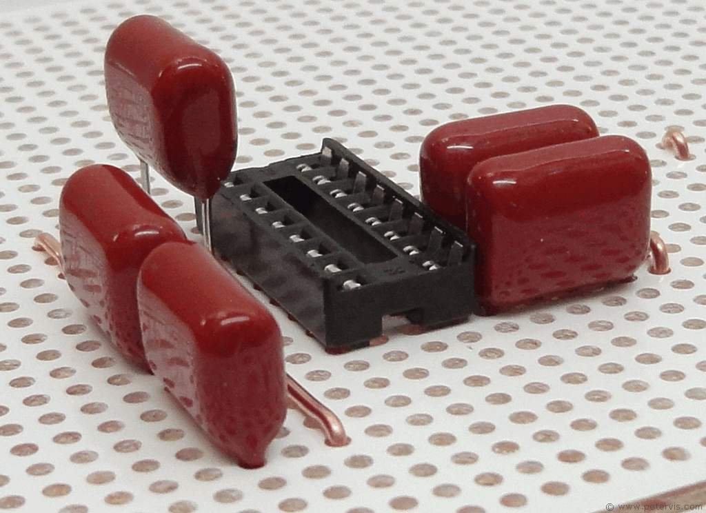
The 0.1-µF capacitors have to be situated very close to the IC, hence I have designed the layout like this with the resistors spread farther out. The green-coloured Mylar polyester film capacitors can be raised slightly, however there is still plenty of space to install the IC.
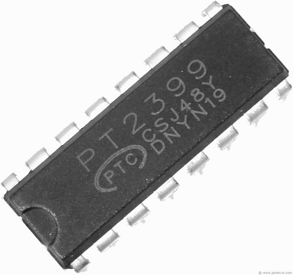
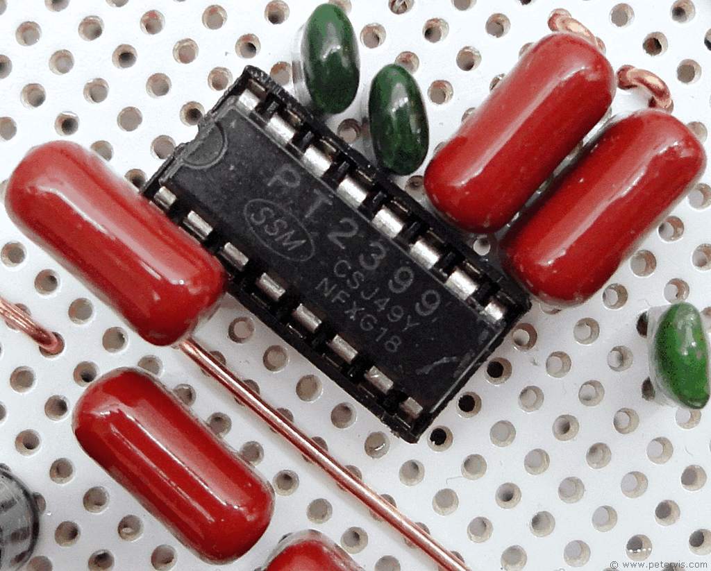
Once you have a completed build that has been tested and double-checked, the IC is the last component to go in. Hence, in the final stages, the circuit will look more like this.
This Article Continues...
Echo and Reverb BasicsGuitar Reverb
Basic Surround Delay Circuit
Basic Echo Circuit
PT2399 Overall Configuration
Testing and Troubleshooting
Pin 6 Hack
Pete's Guitar Reverb Circuit
Track Cuts
Board Links
Circuit Board Component Layout
Completed Board
Switch and Potentiometer Wiring
Chip Socket
Power Supply Circuit Diagram
Power Supply Board Layout
Power Supply Board Cuts and Links
Power Supply Board Completed
Enclosure Preparation
Guitar Reverb Completed Project
Connecting and Testing