PT2399 Circuit Enclosure Preparation
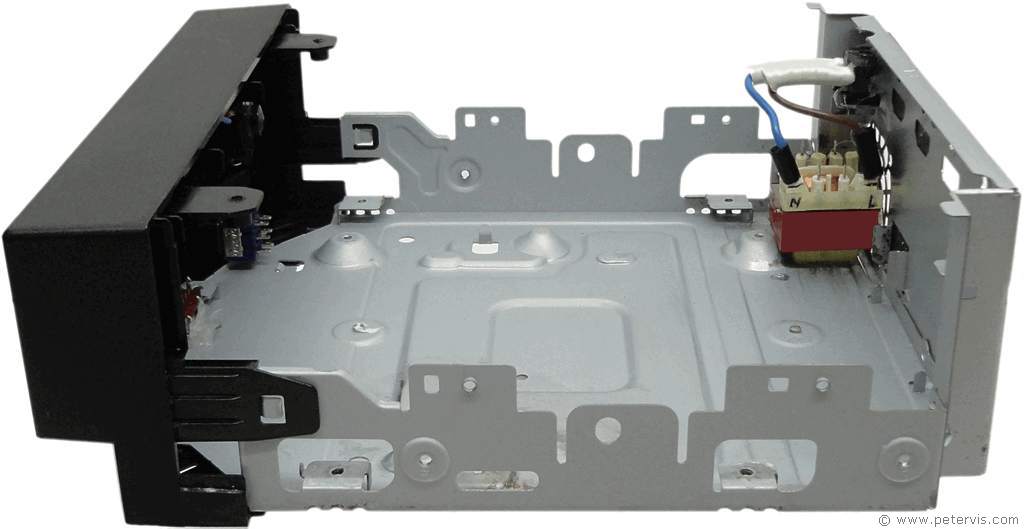
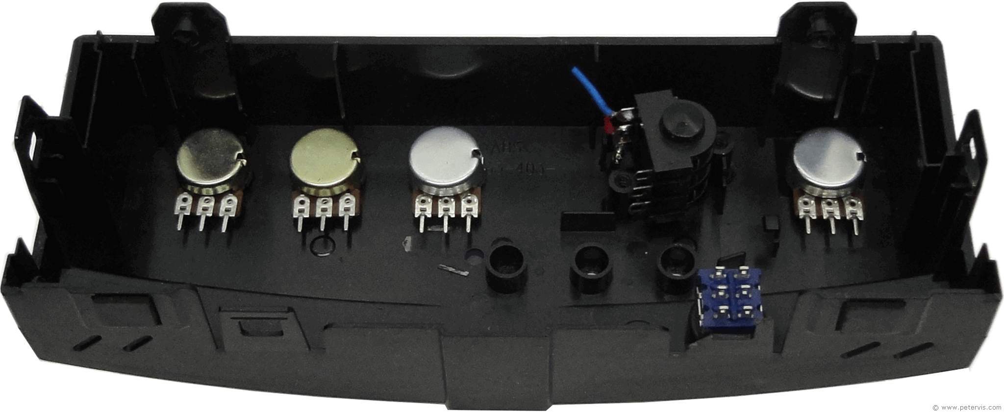
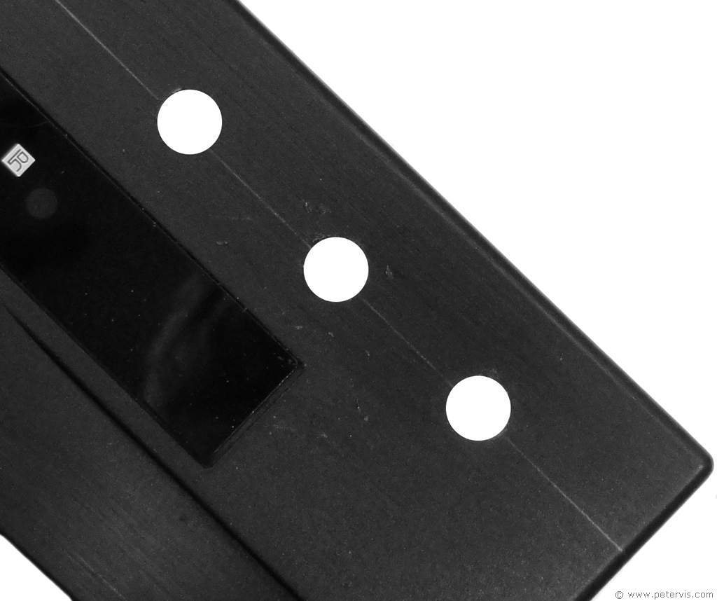
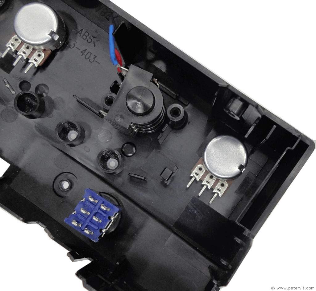
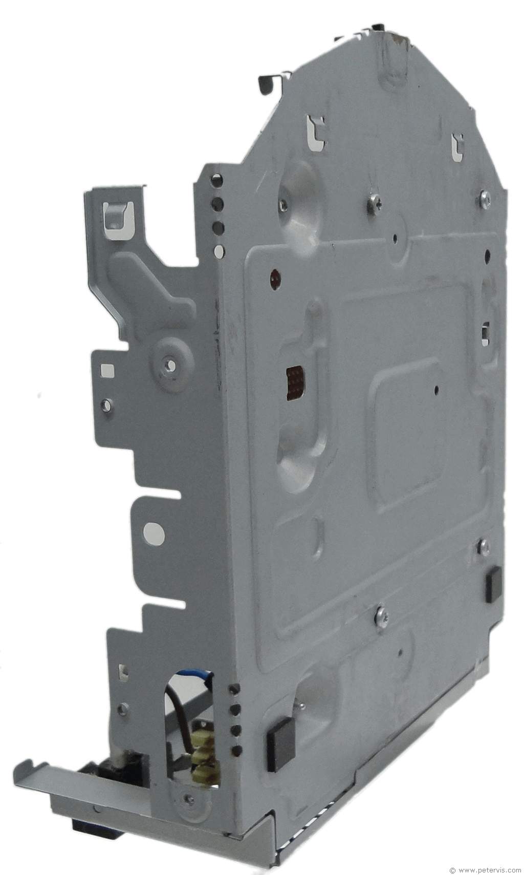
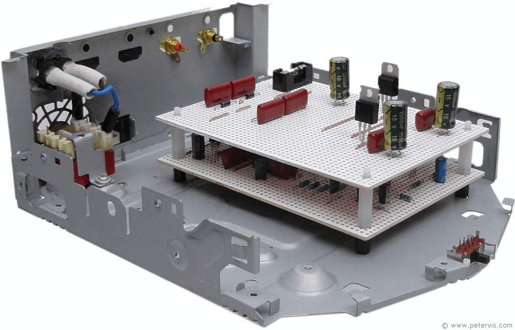
For this guitar reverb circuit, I managed to find a recycled enclosure that had a good chance of working after some modifications. It was ideal for my needs as the front panel was plastic and it is easier to drill holes into it. I drilled holes in the front panel to mount the potentiometers, phase selector switch, and jack socket for the foot switch connection.
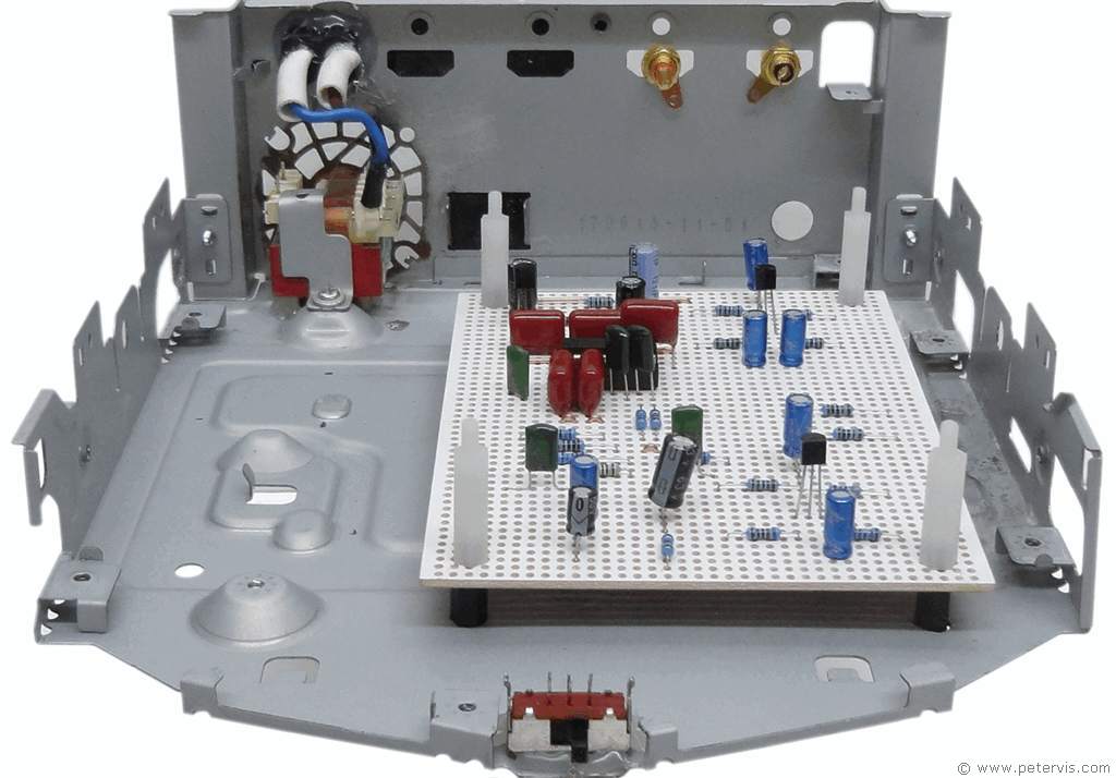
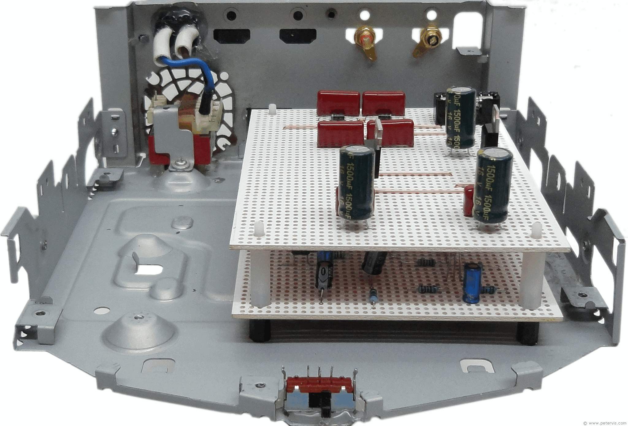
I also had to drill holes for the hex risers for PCB mounting. I decided to stack the boards using hex pillars, however in the final construction I placed the power supply board underneath as I needed to have more access to the main audio board to measure basic parameters from the PT2399 IC.
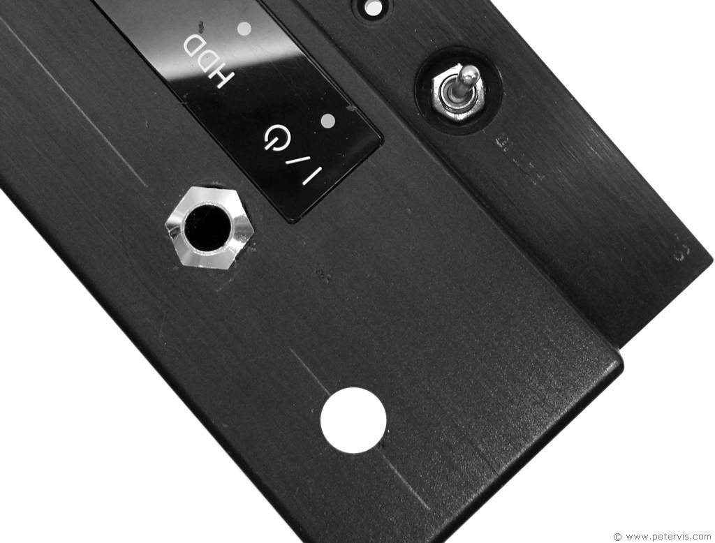
The ¼-inch jack socket is for the trails foot switch; however I have also included a by-pass switch for it when the foot switch is not connected. At the back, I also added a reset switch in case of the start-up bug. Luckily, I have never had to use it!
This Article Continues...
Echo and Reverb BasicsGuitar Reverb
Basic Surround Delay Circuit
Basic Echo Circuit
PT2399 Overall Configuration
Testing and Troubleshooting
Pin 6 Hack
Pete's Guitar Reverb Circuit
Track Cuts
Board Links
Circuit Board Component Layout
Completed Board
Switch and Potentiometer Wiring
Chip Socket
Power Supply Circuit Diagram
Power Supply Board Layout
Power Supply Board Cuts and Links
Power Supply Board Completed
Enclosure Preparation
Guitar Reverb Completed Project
Connecting and Testing
