PT2399 Pin 6 Hack

For guitar reverb, we need the delay to be as short as possible; hence we need the resistance at pin 6 to be as small as possible to achieve the shortest possible delay. Therefore, the problem was, how to keep the resistance at pin 6 as low as possible, but not when the IC is first starting.
It is possible that the resistance at pin 6 causes more current to flow to the digital ground, resulting in start-up issues. This may be the reason for the start-up bug mentioned in the troubleshooting section. In my test circuit, I discovered start-up problems even with 20 kΩ resistance. Consequently, I decided to use a 2N7000 MOSFET transistor to control when the ground connection of the 20 kΩ variable resistor occurs. This transistor has continuous drain current (Id) rating of 200 mA, and continuous gate-source (VGS) voltage of ±20 V. I chose this because it has sufficient current handling capability and it is the cheapest one. In the documentation it states that a resistance as little as 0.5 Ω (produces 31.3 ms delay) is registered by the VCO on pin 6. It occurred to me that using a MOSFET would be advantageous as it behaves as an almost perfect switch with negligible voltage drop across the source and drain junctions. In addition, if you mount the variable resistor on a panel, then make sure the wires are as short as possible to prevent introducing any resistance through them.
The timing to drive the MOSFET is achieved with a simple RC circuit. The 100 kΩ resistor charges the 47 µF electrolytic capacitor to establish a potential difference across the gate junction of the transistor. When the capacitor is charged, the MOSFET conducts and behaves as an almost perfect switch establishing the ground connection for the potentiometer.
As any GCSE student would know, the delay is calculated with the following formula:
Delay = R × C
Hence in this case,
Delay = 100,000 × 47/1000000
Delay = 4.7-seconds
If you used a 33 µF capacitor, then the delay would be 3.3-seconds, and a 22 µF capacitor gives a delay of 2.2-seconds, whilst a 10 µF capacitor gives a delay of 1-second. I chose a largish delay that was noticeable when testing with a meter, however smaller delays up to 1-second could be easily employed.
When the power is disconnected, the capacitor discharges, however since the only discharge path was through the gate junction of the MOSFET, it would take a long time. If the power was cut and instantaneously connected again without giving the capacitor time to discharge, then the same problem could occur. Hence I decided to include a 200 kΩ discharge resistor. However one should bear in mind that if the power is disconnected then one should wait a few seconds before applying the power again. In the final build, I decided to include a reboot switch at the back in case this bug pops up again.
After building the circuit, it is probably a good idea to test the delay to make sure it is there. Before switching ON the power, make sure the pin 6 variable resistor is set to maximum resistance position. My meter has a continuity buzzer, hence I simply connected the probes across the drain and source junctions, and when the transistor conducts, the buzzer is heard.

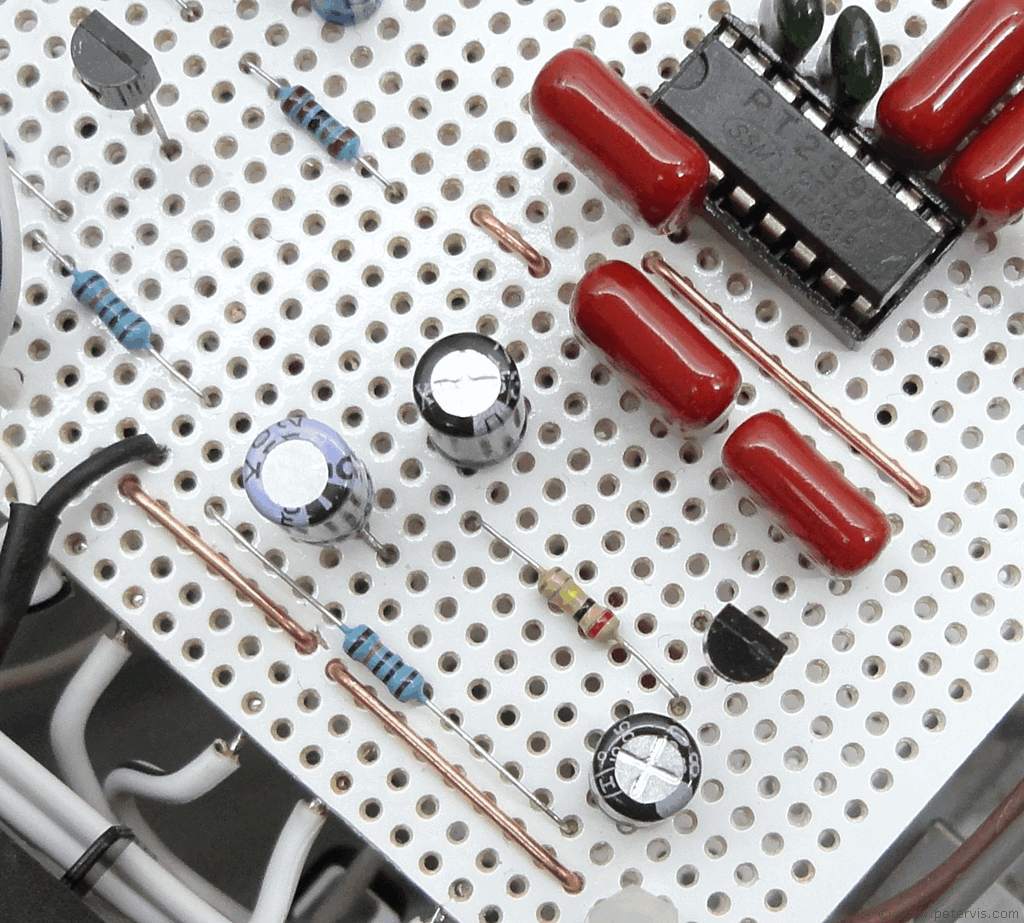
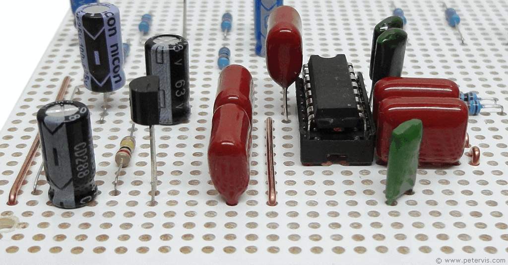
Here is a peek look at how this part of the circuit was implemented in the final build.

This Article Continues...
Echo and Reverb BasicsGuitar Reverb
Basic Surround Delay Circuit
Basic Echo Circuit
PT2399 Overall Configuration
Testing and Troubleshooting
Pin 6 Hack
Pete's Guitar Reverb Circuit
Track Cuts
Board Links
Circuit Board Component Layout
Completed Board
Switch and Potentiometer Wiring
Chip Socket
Power Supply Circuit Diagram
Power Supply Board Layout
Power Supply Board Cuts and Links
Power Supply Board Completed
Enclosure Preparation
Guitar Reverb Completed Project
Connecting and Testing