PT2399 Guitar Reverb Circuit Board Component Layout
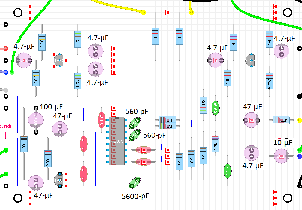
This board layout for the PT2399 guitar reverb circuit is as simple as it gets. As you can see, I managed to get everything on this board which also includes the MOSFET phase splitter and mixer circuits. I have spread the components out as much as possible in order to make the build as simple as possible. Many components also line-up vertically and horizontally, hence one can double-check at a glance if the placement looks odd. The board layout is also very similar to my schematic, so hopefully it will be easy to follow.

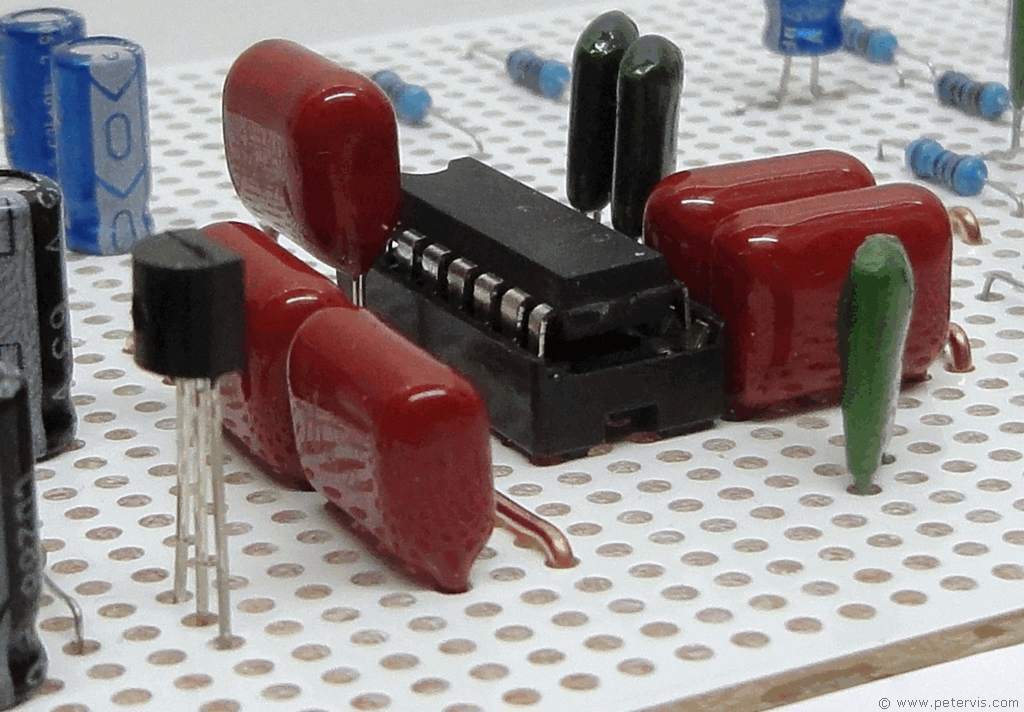
In the top-half of the board, the 2N7000 transistor on the left forms the phase splitter circuit, whilst the transistor on the right forms the mixer part of the circuit. The bottom-half of the circuit is dedicated to the PT2399 IC and its low-pass filter components. The reddish coloured components are the 0.1 µF/100 V metallised polyester-film capacitors. Their lead spacing is 5-holes and they fit easily without any lead bending. Many of the green-coloured Mylar capacitors also fit easily. Hence if you get the correct components, then the build will progress smoothly.

Of course, it is always very prudent to use a chip socket, especially if the IC came from China, as it is possible to receive faulty and fake ICs these days. Since the semiconductors are static sensitive it is also a good idea to use ESD precautions, and minimize heat to the components when soldering.

Here is an overlay view without the track pattern of the board showing. In this diagram one can see the component values more clearly.

I began the build by first installing the metallised polyester film capacitors and the Mylar capacitors.

I decided to complete the left side first.

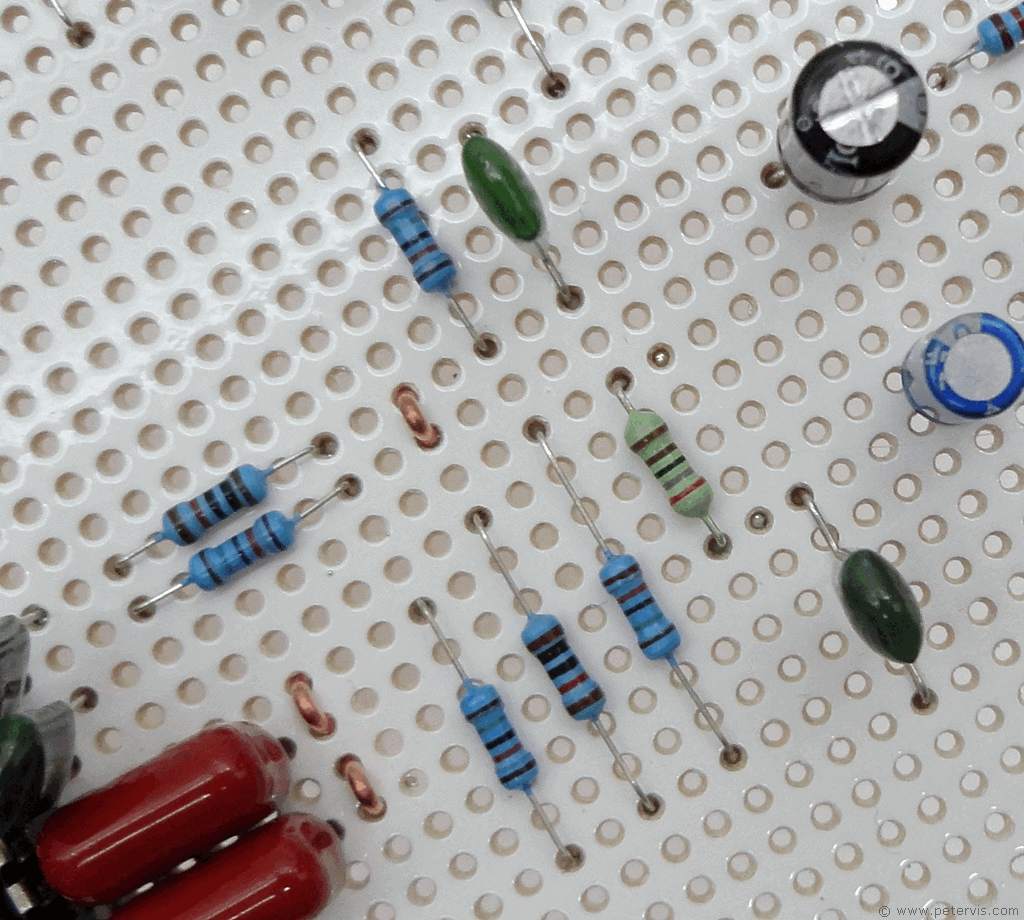
Installing the resistors was fun.

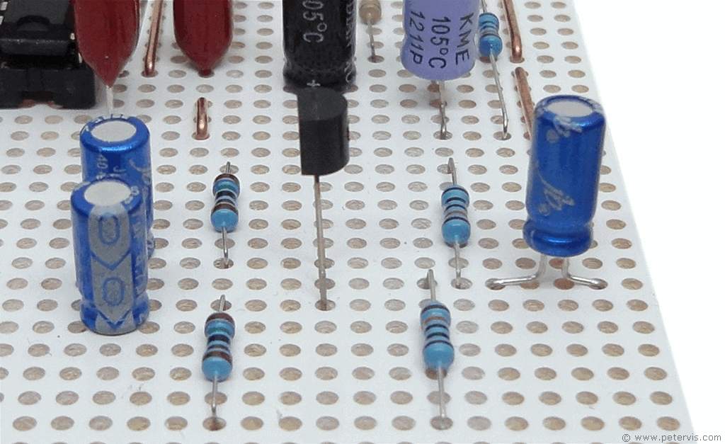
Building the phase splitter circuit was easy as it is just one transistor, four resistors, and three electrolytic capacitors. This is as easy as it gets...
This Article Continues...
Echo and Reverb BasicsGuitar Reverb
Basic Surround Delay Circuit
Basic Echo Circuit
PT2399 Overall Configuration
Testing and Troubleshooting
Pin 6 Hack
Pete's Guitar Reverb Circuit
Track Cuts
Board Links
Circuit Board Component Layout
Completed Board
Switch and Potentiometer Wiring
Chip Socket
Power Supply Circuit Diagram
Power Supply Board Layout
Power Supply Board Cuts and Links
Power Supply Board Completed
Enclosure Preparation
Guitar Reverb Completed Project
Connecting and Testing
