Connecting and Testing the PT2399 Guitar Reverb Circuit

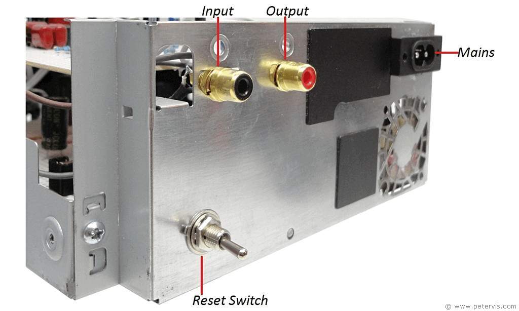
This PT2399 guitar echo/reverb circuit connects between the guitar preamplifier and power amplifier utilising RCA connectors. The circuit has a MOSFET transistor input stage with high gate impedance. Consequently, it can accept AC signals of up to 1 Vp-p without distortion.

MP3 Sample Recordings
MP3 Sample 1 (28-seconds)In this short sample, the delay control is fully off (zero-ohms), and the repeats potentiometer is in the off position too (wiper to ground side). There is a lovely warm reverb happening with this setting, and virtually no background aliasing noise.
MP3 Sample 2 (28-seconds)In this short sample, the delay control is such that the echo is just slightly apparent, whilst the repeats potentiometer is in the off position (wiper to ground side).
MP3 Sample 3 (28-seconds)In this short sample, the delay control is set to produce obvious echo, whilst the repeats potentiometer is in the mid position for slow decay resulting in multiple repeats/echoes. Notice there is also a fuzzy noise in the background, which is just slightly phasing in and out of the range of the low-pass anti-aliasing filters. When any kind of hiss or imperfection gets into the echo loop, it becomes prominent.
IC Computer Reboot Bug
One problem I encountered was when I changed the PT2399 IC and discovered that occasionally its internal digital circuitry failed to start. You can tell it has not started by adjusting the mixer controls to hear for the delayed signal output only. When the IC does not start, there is no delayed output sound, therefore indicating that the digital circuitry within the IC has not started. However switching OFF the power for twenty seconds or so and then switching it back ON (a few times) usually works and starts the IC eventually. If you look at the troubleshooting page there is more information on how to diagnose this issue if your IC does not work first time.
Strangely, the other IC which is from the same manufacturer does not exhibit this issue. My impression is that it may be buggy or it may be a dodgy batch, however whether it spans other versions, by other manufacturers, is something I shall find out in the fullness of time. Nevertheless it is important to be mindful of this bug, and consequently I fitted a reboot switch at the back to easily cut the power.
Guitar Reverb
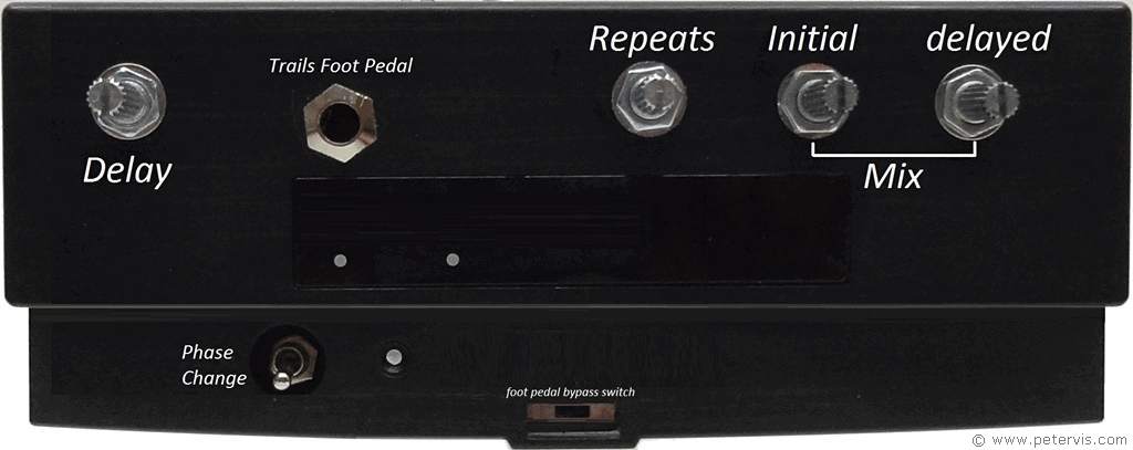
If you are trying to create guitar reverb, you need a very tiny delay, and consequently the resistance has to be in the order of tens of ohms. For the delay variable resistor, I was using a 50 kΩ potentiometer and it worked well in the minimum resistance position, however I wish I had ordered a smaller one to provide more precise control over the smaller resistance range. For guitar reverb, you will very likely keep the delay control to the minimum position to produce just a very tiny delayed signal.
VR2, which is usually called repeats, determines the number of echoes or how quickly the echoes decay. I was using 50 kΩ linear potentiometer, however after testing; I realised that one could use a smaller value to provide better control at the minimum signal end. For guitar reverb, you will very likely want to set this close to the minimum signal side.
Poverty
This is just a basic prototype, however, with hindsight; I wish I had installed a power LED; however my budget did not stretch this far as I was totally tapped out. For the potentiometers I am using the cheap Chinese ones. It is probably better to be mindful of limiting the heat to them when soldering wires to their terminals. This is because, too much heat on the terminals causes the rivet connection to oxidise resulting in intermittent connections.
Sadly, I also no longer have my acoustic or electric guitars for testing purposes because unfortunately I had to pawn them to raise money so I could continue publishing.
This Article Continues...
Echo and Reverb BasicsGuitar Reverb
Basic Surround Delay Circuit
Basic Echo Circuit
PT2399 Overall Configuration
Testing and Troubleshooting
Pin 6 Hack
Pete's Guitar Reverb Circuit
Track Cuts
Board Links
Circuit Board Component Layout
Completed Board
Switch and Potentiometer Wiring
Chip Socket
Power Supply Circuit Diagram
Power Supply Board Layout
Power Supply Board Cuts and Links
Power Supply Board Completed
Enclosure Preparation
Guitar Reverb Completed Project
Connecting and Testing
