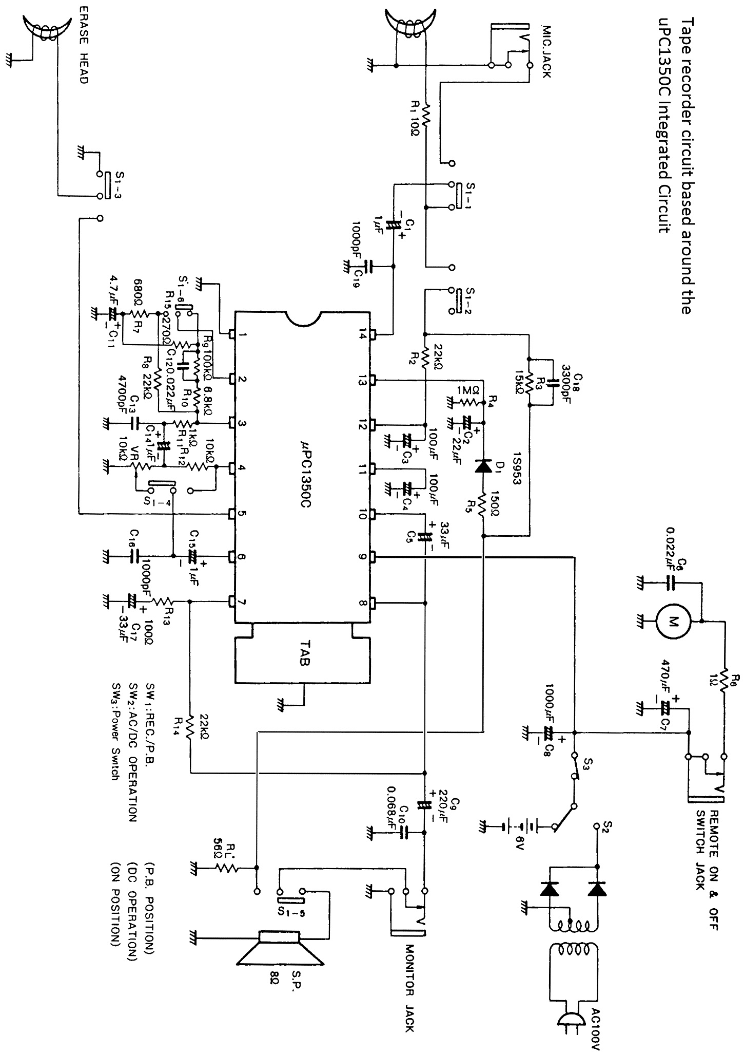
µPC1350C Circuit Diagram

Please note that this is not the actual circuit diagram of the CE-152 but a typical tape recorder schematic based around the µPC1350C integrated circuit. Any tape recorder, which uses this IC, will have a circuit similar to this, and therefore could be useful for repair purposes when nothing else is available. In this circuit, there is no motor regulator circuitry and the motor connects directly to the main power source. It is interesting to see that pin 5 of the IC provides the bias for the erase head, whilst in earlier tape recorders, this function alone would have required many discrete transistors.
This Article Continues...
Sharp CE-152 Tape RecorderSharp CE-152 inside Look
Sharp CE-152 Tape Transport
uPC1350C Audio Amplifier IC
µPC1350C Circuit Diagram
Sharp CE-152 PCB
Sharp CE-152 Chassis
Sharp CE-152 Motor Drive
Sharp CE-152 – Original Condition
How to Clean Battery Terminals
Servicing the Sharp CE-152
Cleaning the Drive Belts
Data Cassette Mod for ZX81
6 V Power Supply – Sharp CE-152
It is Nice Again – Sharp CE-152
